TUTTEE ACADEMY LOGO
broken image
  • Home
  • About Us
  • Subjects 
    • CHEMISTRY
    • BIOLOGY
    • PHYSICS
    • MATHEMATICS
    • PSYCHOLOGY
    • ECONOMICS
    • BUSINESS
    • COMPUTER SCIENCE
    • CHINESE
    • ENGLISH
    • SPANISH
    • IBDP IA / EE
    • IBDP TOK
    • ONLINE TUTORIAL
  • Exam Boards 
    • IBDP
    • IBMYP
    • IGCSE & GCSE
    • HKDSE
    • GCE A-LEVELS
  • Courses 
    • IBDP Tuition
    • GCE A-Level Tuition
    • IBMYP Tuition
    • I/GCSE Tuition
    • HKDSE Tuition
  • Admission Test Prep 
    • PREDICTED GRADE
    • SAT / SSAT
    • UKISET (UK)
    • BMAT
    • UKCAT / UCAT
    • LNAT
    • TMUA (Cambridge)
  • Student Results 
    • IBDP STUDENT RESULTS
    • IGCSE & GCSE MATHEMATICS
    • A-LEVEL STUDENT RESULTS
    • IGCSE STUDENT RESULTS
    • GCSE STUDENT RESULTS (UK)
    • HKDSE STUDENT RESULTS
    • OUR STORIES
  • Question Bank
  • Resources
SCHEDULE A LESSON NOW

PHYS - Electric Circuits

Physics, electric circuits - IBDP | DSE | GCE | IAL | AP Physics

· physics,electricity,circuits

Let's take a look at one IGCSE Physics past paper question on electric circuits 🔌

A student plans to measure the resistance of a piece of wire. He sets up this circuit and finds that it does not work.

broken image

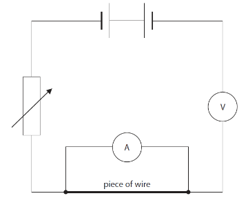
(a) Identify the three errors in this circuit.

  1. Cells are connected with wrong polarity. When two cells are joined as a battery, the positive terminal of one cell should be connected to a negative terminal of another cell.
  2. Ammeter is connected parallel to the piece of wire. Ammeter should always be connected in series to the circuit.
  3. Voltmeter is connected in series. Voltmeter should always be connected in parallel to the element through which voltage is to be measured.

→ To correct the circuit, one of the cells should be flipped and connected, and the position of ammeter and voltmeter should change.

(b) The student uses a correct circuit to obtain these results.

broken image

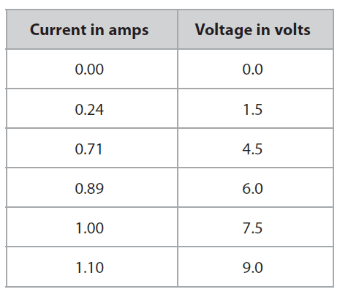
(i) Plot a graph to show the relationship between current and voltage for the wire.

broken image

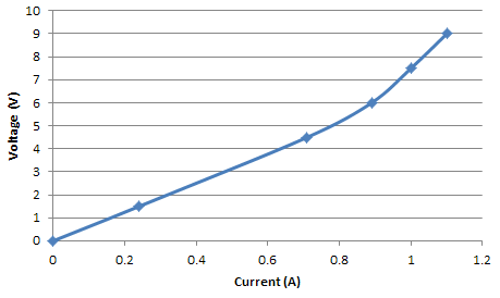
(ii) Find the current when the voltage is 2.5V.

From the graph, the current when the voltage is 2.5V is 0.4A.

(iii) Suggest why the line on the graph curves.

- The temperature of the wire could have changed, thus changing the resistance in the wire.

(iv) Describe what else the student should do to find an accurate value for the resistance of the piece of wire at a constant temperature.

  1. Use an instrument to ensure that the temperature of the wire remains constant.
  2. After some time, disconnect the circuit so that the wire can cool down for a while.
  3. Obtain more voltage-current pair points to plot on the graph.
  4. For each point, repeat the same experiment a few times and find the average value.
  5. Use only the linear part of the graph. For example, in the graph that we plotted, only use the segment of graph that's below 0.7A.
  6. To calculate the resistance of the wire, use Ohm's law; R = V / I
  7. The resistance is equal to the gradient of the voltage vs. current graph.

Wanna Boost Up Your IGCSE Physics?

SIGN UP FOR A FREE TRIAL NOW
Subscribe
Previous
PHYS - Hooke's Law
Next
PHYS - Static Electricity
 Return to site
Profile picture
Cancel
Cookie Use
We use cookies to improve browsing experience, security, and data collection. By accepting, you agree to the use of cookies for advertising and analytics. You can change your cookie settings at any time. Learn More
Accept all
Settings
Decline All
Cookie Settings
Necessary Cookies
These cookies enable core functionality such as security, network management, and accessibility. These cookies can’t be switched off.
Analytics Cookies
These cookies help us better understand how visitors interact with our website and help us discover errors.
Preferences Cookies
These cookies allow the website to remember choices you've made to provide enhanced functionality and personalization.
Save